Preparing a Sheet Metal Fabrication Enquiry
A useful sheet metal enquiry describes a part in the context of the assembly it must fit. The outline shown in a photograph is only one part of that description. Material, thickness, holes, bends, joining details, finish and the dimensions controlling assembly need to be considered together. A clear drawing gives the buyer and supplier a shared reference for those requirements.
This category compares four configurations: flat multi-hole parts, bent brackets, open chassis trays and enclosure bodies. The reference images help distinguish their forms. They do not establish a particular material grade, manufacturing tolerance, load capacity or protection rating. Use the chosen drawing and purchase specification to define the exact supply, then ask for a quotation that identifies the same reference and revision.
Choose the Product Configuration Before Comparing Prices
Begin by deciding which structure is required. A flat plate presents an outline and holes in one plane. A bent bracket adds formed mounting faces. An open chassis tray has a floor and sidewalls with access for assembly. An enclosure body introduces a surrounding box-like form, openings and potentially separate panels or covers.
These distinctions make it easier to communicate the intended part. They should not be used as a shortcut around the drawing. Two brackets may have similar shapes but different hole patterns, sheet thicknesses or bend locations. Likewise, a tray photograph does not show the complete equipment arrangement that it may eventually support.
Laser Cut Sheet Metal Parts: Define the Flat Pattern
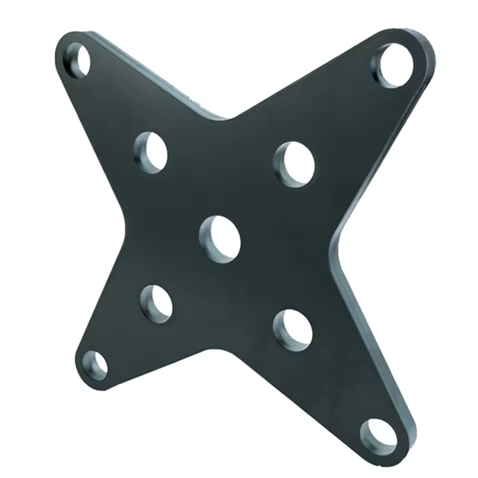
The laser cut sheet metal parts reference is a flat X-shaped plate with several round holes. Use the enquiry to identify the outline, sheet thickness, hole sizes and relative positions. State which dimensions control the fit with other components and which edges have specific appearance or handling requirements.
Agree the manufacturing route for the selected drawing. The photograph identifies a configuration but does not prove how a particular sample was cut or finished. Provide a controlled drawing file and any supporting model, and explain how the two are to be used when they differ. Keep the selected material and required quantity with the same part reference.
Bent Brackets: Review the Finished Shape
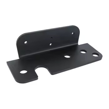
The selected bent sheet metal bracket has two formed mounting faces, holes and a black finish. Its final shape needs to be reviewed with the components that contact those faces. Identify the leg dimensions, bend position, mounting holes and the space available for assembly.
Do not rely only on an unfolded sketch when the installed relationship between faces matters. State the dimensions and interfaces that must be checked on the finished bracket. Identify the required finish separately from the material specification. A black surface does not identify the base metal, coating system or expected service performance.
Chassis Trays: Coordinate the Floor, Walls and Openings
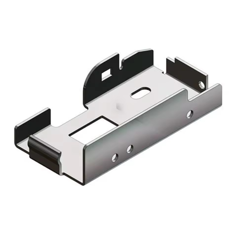
Sheet metal chassis trays provide an open formed arrangement for an equipment assembly. The reference image shows a floor, bent sidewalls, tabs and cutouts. Review the overall envelope and the positions of the features that locate components or provide access.
Include the mating assembly or an interface drawing where possible. This helps distinguish a functional opening from a feature that is merely visible in a photograph. Confirm the parts expected in the supply, the finish and any joining requirements. A tray should not be presented as a complete closed enclosure when the design still requires additional panels or covers.
Enclosures: Specify What Is Included
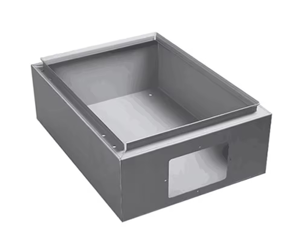
The custom sheet metal enclosure reference has a box-like body, an upper flange and a side opening. A complete enquiry should identify the body, panels, covers, fixings and other components expected in the order. Separate those items from parts that will be supplied by the equipment assembler.
State any project-specific requirements and the evidence needed to support them. The appearance of a box does not establish an environmental rating, electrical compliance or a sealed assembly. Those requirements need an agreed specification and appropriate supporting review. Keep the actual configuration visible in the quotation so that a body-only offer is not confused with a complete enclosure.
Use One Drawing Revision Across the Enquiry
Give every part a clear reference and revision. Use that reference on the drawing, model, enquiry and quotation. When a feature changes, issue a revised record and identify which earlier version is superseded. This reduces the chance that an offer is prepared from an outdated attachment.
If both a drawing and model are supplied, explain which record controls dimensions, tolerances and other requirements. Identify any mismatch before production is agreed. A short revision note is useful when a hole pattern, bend or opening changes, because the visual difference may not be obvious in a small preview image.
State the Material and Thickness
Identify the required sheet material, grade and thickness in the purchase specification. Avoid asking the supplier to infer the material from colour, polish or an old sample photograph. If a material alternative may be considered, describe how it should be proposed and reviewed.
List the material documents needed for the order and the product reference to which they should relate. Keep material requirements separate from surface appearance. A finish reference may help communicate colour or texture, but it does not replace the underlying material specification. Resolve uncertainty before using a quotation as the basis for a final order.
Identify the Dimensions That Control Assembly
Highlight the dimensions and interfaces that affect the mating assembly. These may include mounting-hole positions, contact faces, panel openings, overall envelope or the relationship between formed surfaces. State the required inspection scope rather than relying on a general phrase such as precision part.
For replacement work, distinguish measured dimensions from estimates. Mark any feature that needs confirmation and explain how the original part is used. Photographs from several directions can help the supplier understand the orientation, but they should support the controlled drawing rather than replace it. Keep units consistent across the documents.
Agree Forming and Joining Details
Show the finished shape and identify any bends, tabs, joints or attached components required by the design. Explain which surfaces locate the part in the assembly and where access for fixing or installation is limited. This gives the supplier a more complete picture than an isolated outline.
Ask the proposal to identify any drawing changes that are recommended for the selected manufacturing route. Review those changes before accepting them as part of the supply. A suggested modification should not silently replace the original requirement. Keep the final agreed arrangement with the same drawing revision used by production and inspection.
Define the Finish Through an Agreed Reference
Specify the required appearance and identify the surfaces to which it applies. Where useful, provide an approved sample or a clearly identified finish reference. Explain any areas that have different requirements, including surfaces used for assembly contact or components supplied separately.
Review the finish specification alongside material and dimensional requirements. A visually acceptable surface does not establish that the part fits the drawing, and a dimensionally correct part may still differ from the agreed appearance. Keep the acceptance criteria clear enough for both parties to understand what will be checked at delivery.
Describe Quantity and Order Structure Clearly
State the number of parts required and distinguish an initial sample requirement from the intended production order. If several revisions or related components are being quoted, list them separately with their own quantities. This helps prevent the cost of one version from being applied to another.
Identify which items should be quoted as separate components and which should be supplied as an assembly. Keep optional operations or accessories visible rather than combining them with the base part description. The proposal should make clear what is included, what is excluded and which questions still need to be resolved.
Compare Quotations Against the Same Requirements
Compare offers using the same drawing, material, thickness, quantity, finish and supplied-parts list. Ask each proposal to identify any deviation from the enquiry. A different total may describe a different specification or omit an operation that another supplier has included.
Agree the inspection, packaging and delivery basis as part of the comparison. Clarify ambiguous wording before selecting an offer. The final purchase order should refer to the reviewed configuration and supporting records. A broad phrase such as sheet metal fabrication is useful for organising enquiries, but it is not a complete description of the supplied part.
Plan Inspection and Receiving Records
Before the order is confirmed, identify the dimensional and visual checks expected for the selected part. Keep the drawing revision, parts list, material requirements and finish reference available together. Confirm which records or documents should accompany delivery.
On receipt, compare the delivered items with the agreed specification and record any discrepancy before the parts are assembled. Packaging should help keep similar components and different revisions identifiable. Retain the product reference in the receiving record so that later questions about a hole, bend, finish or supplied accessory can be traced to the correct order.
Send the Complete Part Package
Send Hengke Casting a concise package containing the selected product configuration, controlled drawing, material, thickness, quantity, finish and inspection requirements. Include the mating interfaces or assembly context where they affect fit, and identify any dimension that still needs confirmation.
Use the four product detail pages to organise the discussion, then request a proposal for the exact version required. Keep the enquiry, quotation and final order aligned with one part reference. A clear record of agreed requirements is more useful than relying on a similar-looking photograph when custom sheet metal components are being reviewed for an equipment project.